
Hi,
I am new to this forum and would appreciate any help I can get. We are building an aluminum boat. The superstructure plate is 4mm thick. We have used both TIG (boundaries, butt joints) and MIG welding (all fillet joints) and there is a lot of buckling.
I would upload the pictures soon. However, I am interested to know if there are any procedures you can suggest off hand. Here is what we have been considering -
1. Putting a strong back across the bucked zone and putting additional stiffeners at the back side which is not visible.
2. Heat treating the plate once the strong back has been put and removing the supports once the plate cools. Not sure how good an idea this is. Since this is for the superstructure, we would not quite worry about the mechanical properties being lost.
3. Removing welds where possible, putting supports and re-welding. This would not be possible for it is time consuming and very expensive.
Appreciate any help.
Thanks,
Vishal
Tig welding tips, questions, equipment, applications, instructions, techniques, tig welding machines, troubleshooting tig welding process
- Otto Nobedder
-
Weldmonger

-
Posts:
-
Joined:Thu Jan 06, 2011 11:40 pm
-
Location:Near New Orleans
Welcome, Vishal,
While the best solution would have been prevention, the deed is done, and you need a solution.
One suggestion (try this on scrap first to get a feel): Weld a bead on the outside of the structure, opposite the weld that caused the buckle. If you TIG it, use filler (don't just wash it) so you get the same shrink rate as the original weld, then grind it smooth.
As for prevention on future welds, you can strongback the weld area, and pre-heat the weld area very well (200-250*C). The strongbacks will cause the metal to distort in the direction opposite the draw the weld will cause, so the end result (wait until cool to cut the strongbacks off) should be near-neutral in distortion.
There are others here with more marine aluminum experience than I have, who may give better advice, so stick to a scrap-metal test until you see the result and/or hear from others.
Steve S
If you look at even professional yards that build ships/yachts in aluminum, distortion is just the nature of the beast on flat panels. Otherwise, welding is left to outside corner joints and oragami practices where possible on smaller craft. Forget TIG in the flat areas, speed and minimal heat calls for MIG where possible. Larger panels may be welded off of the hull and corrected before installed where possible. Many welded aluminum boats the panels are designed with strategic distortion in mind in which to minimize it.
I used to have to join panels of 11 gauge and would have to sandwich them between rather large pieces of 1/2" steel plate to arrive at panels that were nearly free of distortion. I have been welding aluminum in the marine industry since 1988. I inevitably built a boat out of wood, which perplexed all of my peers, considering. I wanted a perfect finish, which is nearly impossible to effectively acheive with fiberglass or aluminum.
When I weld bulkheads to aluminum panels, I create a flange on the frame or bulk head. Either with a press break or pre fabricated with welded outside corner joints. Then weld the edge of the flange as a lap joint instead of an inside corner. This will greatly reduce distortion.
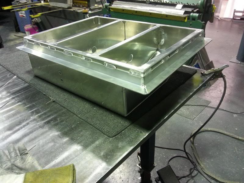
Here is a somewhat relative example with a fuel tank built of 11 gauge 5052 with TIG. All I got with it was the end plates and 2 flat bulkheads/slosh baffles.
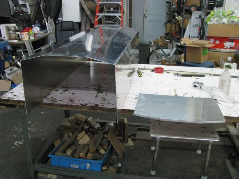
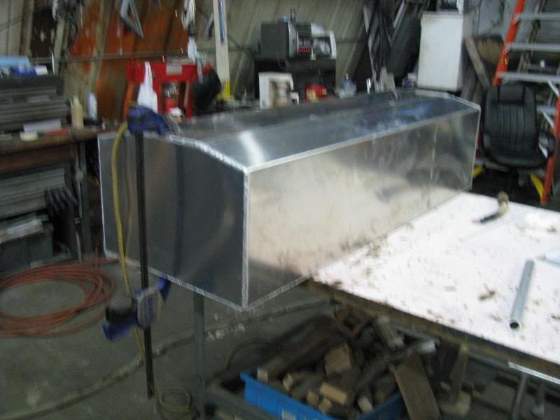
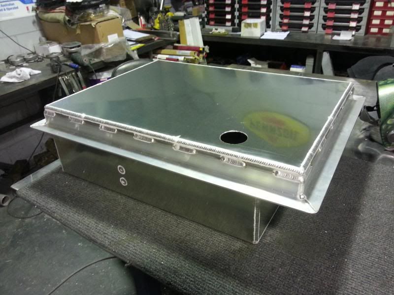
If I would have welded them as supplied, I would have been chasing distortion and ended up with an oil canned tank that may pop in and out once fuel was added, even with just temperature changes. I instead welded 1" flanges to each of the central bulkheads and stitched the laps with TIG, and added a few rosettes in drilled holes for good measure. Rosettes will cause distortion but it is localized in the doubler that the flange creates, much of which can be corrected with hammer and dolly if it really matters that much. I don't have a photo of that part of the process, but here is a photo and you can see where the stitches are on the skin of this tank on the long sides. It is also apparent that there is minimal distortion. I weld it with 250 amps and quickly and clamp in between stitches where possible. Or, forcing a brace from side to side to keep the flange ridiculously tight between welds.
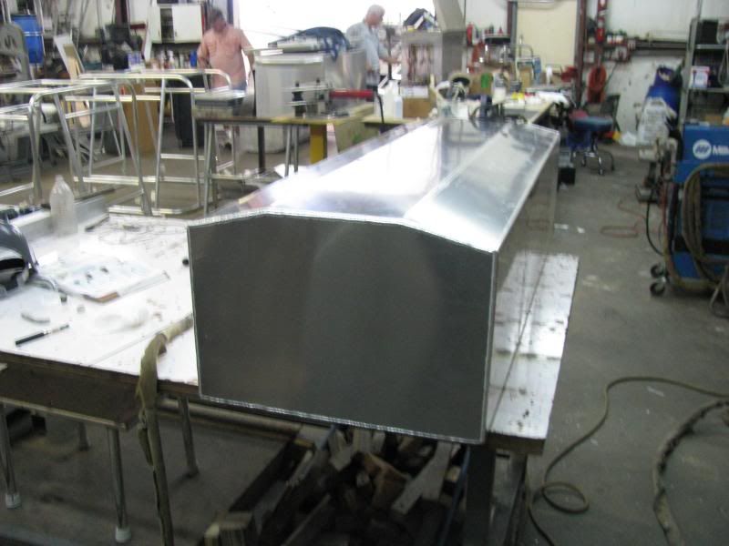
You can see the set of 2" stitches on the far end of the side. There is another identical set that is blocked by the glare off of the table. I could have filled in between the stitches after the fact and the distortion would have been minimal.
There is some other, nonconventional methods that employs face beveled (lap joints with the outside corners beveled) backer strips for extreme situations, but that is an art that would be somewhat difficult to explain and is a rather tedious process. It essentially changes the direction of shrinkage of the fillets.
I used to have to join panels of 11 gauge and would have to sandwich them between rather large pieces of 1/2" steel plate to arrive at panels that were nearly free of distortion. I have been welding aluminum in the marine industry since 1988. I inevitably built a boat out of wood, which perplexed all of my peers, considering. I wanted a perfect finish, which is nearly impossible to effectively acheive with fiberglass or aluminum.
When I weld bulkheads to aluminum panels, I create a flange on the frame or bulk head. Either with a press break or pre fabricated with welded outside corner joints. Then weld the edge of the flange as a lap joint instead of an inside corner. This will greatly reduce distortion.
Here is a somewhat relative example with a fuel tank built of 11 gauge 5052 with TIG. All I got with it was the end plates and 2 flat bulkheads/slosh baffles.
If I would have welded them as supplied, I would have been chasing distortion and ended up with an oil canned tank that may pop in and out once fuel was added, even with just temperature changes. I instead welded 1" flanges to each of the central bulkheads and stitched the laps with TIG, and added a few rosettes in drilled holes for good measure. Rosettes will cause distortion but it is localized in the doubler that the flange creates, much of which can be corrected with hammer and dolly if it really matters that much. I don't have a photo of that part of the process, but here is a photo and you can see where the stitches are on the skin of this tank on the long sides. It is also apparent that there is minimal distortion. I weld it with 250 amps and quickly and clamp in between stitches where possible. Or, forcing a brace from side to side to keep the flange ridiculously tight between welds.
You can see the set of 2" stitches on the far end of the side. There is another identical set that is blocked by the glare off of the table. I could have filled in between the stitches after the fact and the distortion would have been minimal.
There is some other, nonconventional methods that employs face beveled (lap joints with the outside corners beveled) backer strips for extreme situations, but that is an art that would be somewhat difficult to explain and is a rather tedious process. It essentially changes the direction of shrinkage of the fillets.
Miller ABP 330, Syncrowave 250, Dynasty 300 DX.
Honorary member of the Fraternity of Faded Tee Shirts.
Honorary member of the Fraternity of Faded Tee Shirts.

awill4wd
- awill4wd
-
Active Member

-
Posts:
-
Joined:Thu Jan 31, 2013 3:57 am
-
Location:Berwick, Melbourne, Australia
Like TamJeff I use the same system of folded edge baffles and for me end plates on the Mustang tanks we build.
I also try to leave the top off till last and get all the mounts in place as it's easier to clamp them in position with lots of clamps rather than chase the Aluminium shell as it wants to move away from the mounting angles in this case.
If it's possible on the lids I'll do a very slight criss cross to help prevent the "oil can" effect as the lid is welded to the tank.
Using the fabrication techniques on these tanks allows most of my welding to be lap welds around the entire tank shell.
Regards Andrew from Oz.
We are Tig welders, gravity doesn't worry us.
Miller Dynasty 350
OTC hybrid wave 300 amp inverter Tig at work (Now retired)
Kemppi MLS 2300 inverter, 230 amps of welding brilliance for home use
Miller Dynasty 350
OTC hybrid wave 300 amp inverter Tig at work (Now retired)
Kemppi MLS 2300 inverter, 230 amps of welding brilliance for home use
Like on the tank I posted above, I always ask for a cross break on the flat panels. If I got to order them personally, I would get what I ask for. But I never get them. Why? Because the powers that be are not welders, or fabricators and somehow, vicariously through my skills over the years, have somehow changed places with me and became the experts by mere association in which to claim that they are not necessary. It sux when your deciders can't weld well enough to experience what we may bitch about at least once.
Sheet metal is not my favorite thing to do, even though that is where I started. I like the layout challenges of it, but not much for the assembly.
Very nice work on the tank above. I would gladly pass mine off to you.
Sheet metal is not my favorite thing to do, even though that is where I started. I like the layout challenges of it, but not much for the assembly.
Very nice work on the tank above. I would gladly pass mine off to you.
Miller ABP 330, Syncrowave 250, Dynasty 300 DX.
Honorary member of the Fraternity of Faded Tee Shirts.
Honorary member of the Fraternity of Faded Tee Shirts.
Return to “Tig Welding - Tig Welding Aluminum - Tig Welding Techniques - Aluminum Tig Welding”
Jump to
- Introductions & How to Use the Forum
- ↳ Welcome!
- ↳ Member Introductions
- ↳ How to Use the Forum
- ↳ Moderator Applications
- Welding Discussion
- ↳ Metal Cutting
- ↳ Tig Welding - Tig Welding Aluminum - Tig Welding Techniques - Aluminum Tig Welding
- ↳ Mig and Flux Core - gas metal arc welding & flux cored arc welding
- ↳ Stick Welding/Arc Welding - Shielded Metal Arc Welding
- ↳ Welding Forum General Shop Talk
- ↳ Welding Certification - Stick/Arc Welding, Tig Welding, Mig Welding Certification tests - Welding Tests of all kinds
- ↳ Welding Projects - Welding project Ideas - Welding project plans
- ↳ Product Reviews
- ↳ Fuel Gas Heating
- Welding Tips & Tricks
- ↳ Video Discussion
- ↳ Wish List
- Announcements & Feedback
- ↳ Forum News
- ↳ Suggestions, Feedback and Support
- Welding Marketplace
- ↳ Welding Jobs - Industrial Welding Jobs - Pipe Welding Jobs - Tig Welding Jobs
- ↳ Classifieds - Buy, Sell, Trade Used Welding Equipment
- Welding Resources
- ↳ Tradeshows, Seminars and Events
- ↳ The Welding Library
- ↳ Education Opportunities