I've come to the conclusion I want a pedal for my TIG welder. I'm used to not being able to change the current when welding but I just can't get to grips (ha ha) with this torch style that my machine has:
http://arweld.net/userfiles/image/008.JPG
I see americans use much slimmer handles and with much more flexible torch hoses and I think, that looks nice. But I don't have a pedal, I couldn't use such a torch unless I mounted a trigger on it, which kinda brings me back to square one doesn't it? i looked up what a pedal for a kemppi would cost and it said 800 euros!!!!??? I found some 3rd party from the UK for 250, still too steep for my shallow pockets.
Only one way to go, build my own. Which turned out to be more difficult than I thought for this welder. It doesn't work like most of you are used to, you set the max current on the welder and that's it. Any remote, hand or foot (I have a hand remote, meant for stick welding) takes over completely. So Kemppi pedals have a min and max adjustment on the pedal itself. I would have to replicate this and I have no electronics skill or experience. Fortunately I was able to get a schematic from Kemppi, and with the help of some electronics forums I was able to start building:
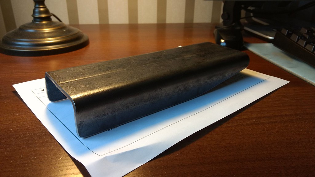
Started out with a scrap u-beam I cut to shape with the portaband
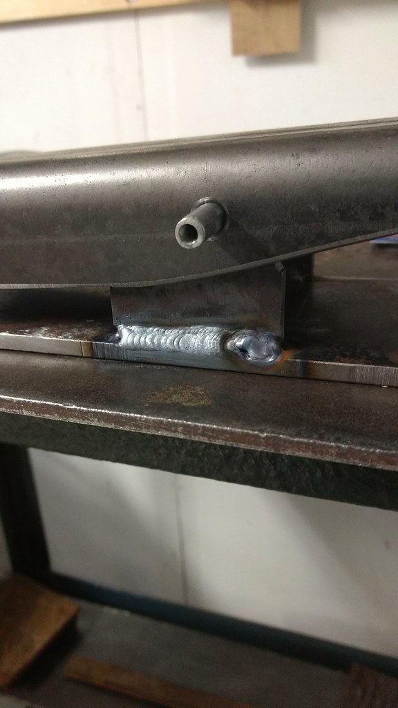
Bottom plate from scraps:
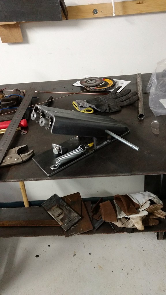
Potentiometers for min and max mounted on the front, copying the kemppi design here. I found some sprockets that fit on the pots, thought they looked cool as knobs:
I then made the circuit I had designed in kicad:
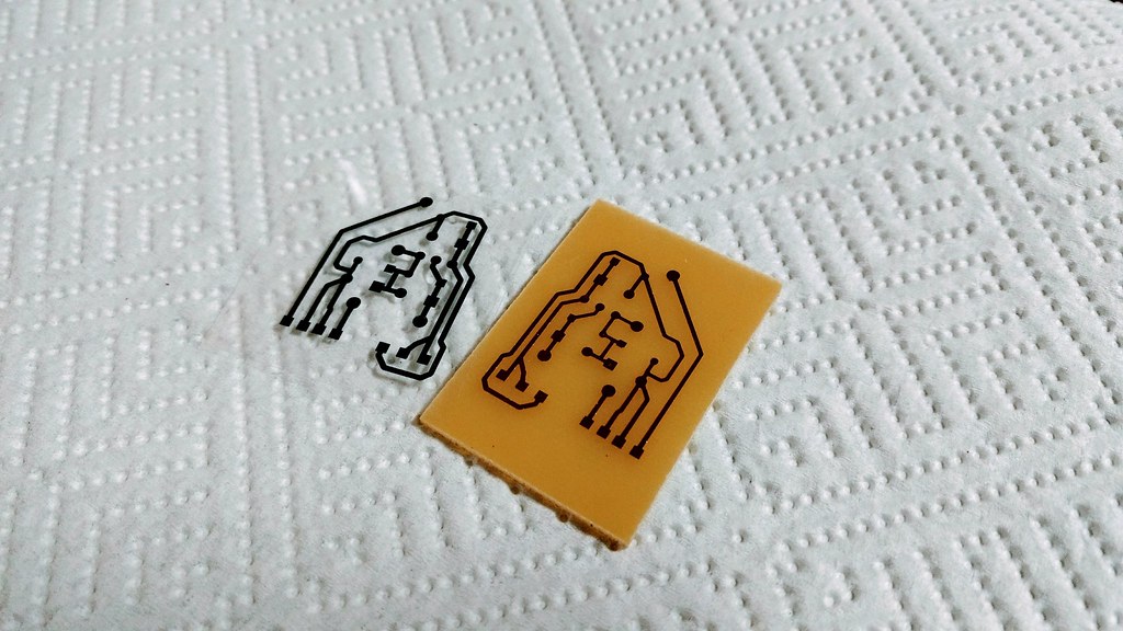
Electronics installed:
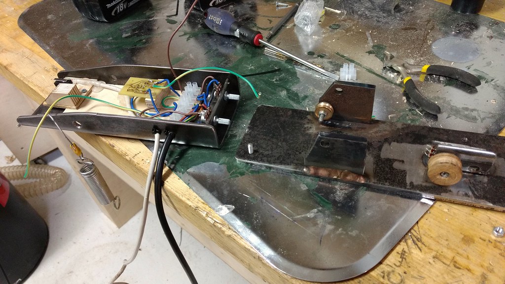
This is where I am now, not yet completely finished, I lack a 4-pin amphenol connector for the microswitch which has a separate connector, but the pedals current adjustment worked correctly when I tested it so all I need is that part (in the mail).
I might redesign it yet, it might make more sense to put the electronics and the min and max adjustment in a separate box on the welder itself and just have the switch and main pot in the pedal, it wold be easier to adjust that way instead of reaching down the front of the pedal.
I've really learned a lot from doing this project, about electronics, PCB design and just how this whole setup works, if it breaks I know I can fix it myself.
General welding questions that dont fit in TIG, MIG, Stick, or Certification etc.
Artie F. Emm
- Artie F. Emm
-
Weldmonger
-
Posts:
-
Joined:Thu Jul 24, 2014 7:53 am
Good morning! Very impressive build. To start with zero electronics experience and a schematic means you learned it all the hard way. Good on ya!
Dave
aka "RTFM"
aka "RTFM"
exnailpounder
- exnailpounder
-
Weldmonger
-
Posts:
-
Joined:Thu Dec 25, 2014 9:25 am
-
Location:near Chicago
That is a sturdy build indeed
Like the gears as pot knobs
What will the pcb do?
Like the gears as pot knobs
What will the pcb do?
Pictures from my scrap collection:
http://forum.weldingtipsandtricks.com/v ... f=9&t=5677
- MosquitoMoto
-
Weldmonger
-
Posts:
-
Joined:Sat Aug 01, 2015 8:38 am
-
Location:The Land Down Under
Impressive and also kinda Steampunk - I like it.
Dennis, I will say this - the torch that came standard with my machine was also one of those bloody awful, bulky 'Euro style' (Trafimet?) torches with the switch.
I absolutely hated it.
I purchased a lightweight tube-style torch online and attached a cheap paddle switch. Trust me, if you ever need the option of a more nimble torch with a switch on it, this setup is MUCH better.
If I ever found the person responsible for designing those awful Euro style torches, the next person to see his torch would be his Proctologist.
Kym
kiwi2wheels
- kiwi2wheels
-
Ace
-
Posts:
-
Joined:Sun Feb 17, 2013 10:27 am
MosquitoMoto wrote:Impressive and also kinda Steampunk - I like it.
Dennis, I will say this - the torch that came standard with my machine was also one of those bloody awful, bulky 'Euro style' (Trafimet?) ..................................
If I ever found the person responsible for designing those awful Euro style torches, the next person to see his torch would be his Proctologist.
Kym
Right on Kym !
Thanks guys!
So the PCB is all about modifying the resistance range of the potentiometer, while maintaining it's full physical "throw". I can see this being useful, if you want a narrow range with lots of "resolution" in your pedal for some reason, then you could set it say 50-100A and get a 50A range on your pedal, or less.
Well based on what I've found out how these things work I believe it modifies the range of the 10k pot that adjusts the current. Without the PCB and the two other pots doing their thing, the potentiometer alone would just be a 10k pot and if you hooked that up alone it would change the amperage between 0-300A (range of this machine). That's basically how the hand remote that I got with the machine works, just a 10K pot in a plastic housing is all it is.AndersK wrote:That is a sturdy build indeed
Like the gears as pot knobs
What will the pcb do?
So the PCB is all about modifying the resistance range of the potentiometer, while maintaining it's full physical "throw". I can see this being useful, if you want a narrow range with lots of "resolution" in your pedal for some reason, then you could set it say 50-100A and get a 50A range on your pedal, or less.
- MosquitoMoto
-
Weldmonger
-
Posts:
-
Joined:Sat Aug 01, 2015 8:38 am
-
Location:The Land Down Under
Just one thing;
I love the knobs on the front of the pedal but they wouldn't work for me. Your setup and technique might be different but while welding I am forever moving that pedal around, generally with a haphazard push of the foot, as I reposition myself to tackle another part of the project I'm on.
You are probably way tidier than I am (most people are...) and won't have any such problems, but if I had knobs on the front of my pedal I'm sure they'd get moved about as I accidentally shoved the pedal into whatever was on the floor at the time.
Perhaps I should just tidy up...
Kym
I try to keep it tidy as I get frustrated when things are in disarray, though in a project things just happen to get like that until it's over. It's a constant battle. But you are right, I might in the future move the PCB and min & max pots into their own control box and attach it permanently on top of the welder or perhaps on the side.
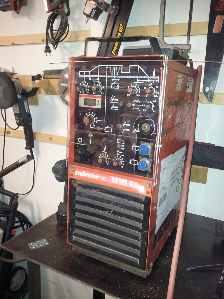
This is my welder, old school slow frequency inverter, squeals in use, made in '94 I think, a sticker on it says serviced in 2011:
What you see there is my attempt to add a dust cover. The intake under has a filter too, it's a solid old unit.
This is my welder, old school slow frequency inverter, squeals in use, made in '94 I think, a sticker on it says serviced in 2011:
What you see there is my attempt to add a dust cover. The intake under has a filter too, it's a solid old unit.
- MosquitoMoto
-
Weldmonger
-
Posts:
-
Joined:Sat Aug 01, 2015 8:38 am
-
Location:The Land Down Under
Kemppi, yeah?
Quality machines, and popular here in Australia, too, although I have heard that some (maybe all?) models use non-standard sockets/attachment points for torches, earth and pedal.
I imagine that there are many good years in that one yet. And I like your dust cover!
Kym
Quality machines, and popular here in Australia, too, although I have heard that some (maybe all?) models use non-standard sockets/attachment points for torches, earth and pedal.
I imagine that there are many good years in that one yet. And I like your dust cover!
Kym
Yeah it's a kemppi, they do seem to use their own versions, but up here in Finland and the nordics I don't really know if they got a standard at all, everyone seems to run their own connections. My machine uses amphenol ms3106a connectors, 4 and 10 pin outlets. I think modern kemppis use 7 pin amphenols and route everything through that one socket.
Dust cover broke unfortunately, the material was very brittle after heat forming. I should get some real polycarbonate some day.
Talent.
Pixies and smoke scare me away from attempting someything like that.
Everlast 250EX
Miller 250 syncrowave
Sharp LMV Vertical Mill
Takisawa TSL-800-D Lathe
Coupla Bandsaws,Grinders,surface grinder,tool/cutter grinder
and more stuff than I deserve(Thanks Significant Other)
Miller 250 syncrowave
Sharp LMV Vertical Mill
Takisawa TSL-800-D Lathe
Coupla Bandsaws,Grinders,surface grinder,tool/cutter grinder
and more stuff than I deserve(Thanks Significant Other)
Thanks, yeah it sounds hard but I had a lot of help from electronics forums and google and also the local electronics store. The most difficult part was learning the cad program, I have some experience with sketchup and other graphics programs so that helped a bit.FoxZulu wrote:Fantastic job. Did you make the pcb yourself?
With a pre-sensitised board all I had to do was to print the design on some OH film, peel of the protective layer and sandwich it together firmly and place it under a light source that emits UV (used a CFL lamp), then develop (immerse) it in a lye solution afterwards, then it's ready for etching. Which was just mixing some power and water together and letting it soak.
I used to fight with my pedal all the time and got really tired of that shit. Now I position it before I start welding and when it moves, oh well. I'll use it sideways under my foor and squeeze it with my heal or if it gets really awkward then I'll just kick it over to the other foot and keep going. I'm slightly abusive with my pedal so I'm not sure those knobs would work for me either.MosquitoMoto wrote:while welding I am forever moving that pedal around, generally with a haphazard push of the foot, as I reposition myself to tackle another part of the project I'm on.
Raymond
Everlast PowerTIG 255EXT
rahtreelimbs
- rahtreelimbs
-
Heavy Hitter
-
Posts:
-
Joined:Mon Jun 14, 2010 10:39 pm
rahtreelimbs
- rahtreelimbs
-
Heavy Hitter
-
Posts:
-
Joined:Mon Jun 14, 2010 10:39 pm
RamboBaby wrote:He already explained that.rahtreelimbs wrote:I never saw a pedal that had a circuit board........why does yours need one?
Ok...thanx.
Check a new ESAB pedal then.....rahtreelimbs wrote:I never saw a pedal that had a circuit board........
It "talks" with the machine thru a CAN-bus. Like, hey the bloke that stomps on me wants 100 A, wait now give me 105 A. Crap he cant decide, gimme 103 A now....
Kills the aftermarket brands and makes it very difficult to copy unless you have skills in both electronics, programming and have access to their can protocol.
Pictures from my scrap collection:
http://forum.weldingtipsandtricks.com/v ... f=9&t=5677
If that's what you did with "no electronics experience" I don't even know what I would classify as........
Very nice build and the knobs look awesome, I think your idea of putting most electronics in a seperate box is a good idea as you might get tired of reaching down and adjusting but then again, maybe not. Either way, looks great.
if there's a welder, there's a way
x2Olivero wrote:I think your idea of putting most electronics in a seperate box is a good idea
Either way, looks great.
Think I will do the same, put the pot in a separate box and make it possible to use the torch switch without changing connectors.
Too often I change the max current while repositioning the pedal with my feet.
Pictures from my scrap collection:
http://forum.weldingtipsandtricks.com/v ... f=9&t=5677
I'm doing something similar. Have been using a Weldcraft RCCS 14 for 5 years but now need foot pedal. The dial is actually a spur gear at around 13 teeth to the inch so I used a 1/2"x 13 UNC tap to thread the inside of a plastic pipe, then cut the pipe into strips to make a rack. Simple and fast.
Same kind of pedal but a pull-pull cable system to pull the rack. No mods to the RCCS 14
JFF45
- JFF45
-
Active Member
-
Posts:
-
Joined:Thu Dec 29, 2016 6:13 pm
-
Location:Morayfield, QLD Australia
My first time replying to a thread on this forum so hope it works..
The pedal supplied with my machine had a 1k pot on the side that was supposed to limit the max amps but when I opened it to see why it didn't work I found it had no wires connected to it. It was only there for the sales brochure pic, lol.
I added and wired in a 25k linear pot to limit the range but found the knob on the pedal itself not very practical to use down there so I removed it and put it in its own box close to the machine.
...
- IMG_4775.JPG (48.06 KiB) Viewed 4412 times
John
Return to “Welding Forum General Shop Talk”
Jump to
- Introductions & How to Use the Forum
- ↳ Welcome!
- ↳ Member Introductions
- ↳ How to Use the Forum
- ↳ Moderator Applications
- Welding Discussion
- ↳ Metal Cutting
- ↳ Tig Welding - Tig Welding Aluminum - Tig Welding Techniques - Aluminum Tig Welding
- ↳ Mig and Flux Core - gas metal arc welding & flux cored arc welding
- ↳ Stick Welding/Arc Welding - Shielded Metal Arc Welding
- ↳ Welding Forum General Shop Talk
- ↳ Welding Certification - Stick/Arc Welding, Tig Welding, Mig Welding Certification tests - Welding Tests of all kinds
- ↳ Welding Projects - Welding project Ideas - Welding project plans
- ↳ Product Reviews
- ↳ Fuel Gas Heating
- Welding Tips & Tricks
- ↳ Video Discussion
- ↳ Wish List
- Announcements & Feedback
- ↳ Forum News
- ↳ Suggestions, Feedback and Support
- Welding Marketplace
- ↳ Welding Jobs - Industrial Welding Jobs - Pipe Welding Jobs - Tig Welding Jobs
- ↳ Classifieds - Buy, Sell, Trade Used Welding Equipment
- Welding Resources
- ↳ Tradeshows, Seminars and Events
- ↳ The Welding Library
- ↳ Education Opportunities